Wednesday 22 July 2015
Sunday 19 July 2015
Interfacing Ultrasonic Sensors with Atmega
About Ultrasonic Sensors:
An ultrasonic sensor module has an ultrasonic transmitter, receiver and a control circuit.
It has 4 pins:
Trigger
Echo
Vcc
Ground
When we give trigger signal, the module will send 8 cycles of 40kHz ultrasonic pulses. These pulses go into the air, and at the same time, the ECHO pin becomes HIGH. After reflection from any any object/obstacle on its path they are reflected back and are received by the receiver. Now the ECHO pin goes to LOW state.

So, our code has to perform two task:
1. Give Trigger Signal.
2. Based on the time for which ECHO pin remains HIGH, calculate the distance.
We can keep a note of time by two methods:
1. Polling. (Run a while loop).
2. Interrupt. (Stop the timer when ECHO pin becomes LOW).
Calculating Distance:
Velocity of ultrasonic signal = velocity of sound waves = v = 340 m/s.
Distance in cm = v * t (in microseconds) / 2.
d = t/58 cm.
Based on the above calculations, the code for Atmega32 is:
#include<avr/io.h>
#include<util/delay.h>
#include<compat/deprecated.h>
#include"uart.c"
#include"uart.h"
#include<avr\interrupt.h>
#include<stdlib.h>
uint8_t counter;
void ultraj(void);
int calculate(void);
void main()
{
DDRC = 0xFF;
PORTC = 0;
uart_init(UART_BAUD_SELECT(9600,F_CPU));
while(1)
{
ultraj();
}
}
void ultraj()
{
PORTC = 0xFF;
DDRA = 0x01;
char buf[40] = {0};
int distance;
cbi(PORTA,0);
_delay_us(10);
sbi(PORTA,0);
_delay_us(10);
cbi(PORTA,0);
TCNT0 = 0x00;
TIMSK = (1<<TOIE0);
cbi(PORTA,1);
sei();
while(!(PINA&(1<<1)));
TCCR0 = 0x03;
while(PINA&(1<<1));
TCCR0 = 0x00;
distance = calculate();
itoa(distance,buf,10);
uart_puts("disttnace : ");
uart_puts(buf);
uart_puts("\n\r");
_delay_ms(70);
}
int calculate()
{
int timea,timeb,timec,timed;
int dist;
char chara[20] = {0};
timea = counter*255;
timeb = TCNT0+timea;
timec = timeb*2.44;
timed = (timec/58);
itoa(timed,chara,10);
uart_puts(chara);
dist = timed;
return dist;
}
ISR(TIMER0_OVF_vect)
{
counter++;
}
Counting Real Time RPM with IR sensors
RPM of robot may change due to:


The output of IR sensor will go to a interrupt. Now, whenever the color changes from black to white, output will go from LOW to HIGH. Hence, "RISING" state should be chosen for interrupt.
RPM value is now stored in EEPROM and you can check it..
Important point to note here is the distance between sensor and the wheel, and also the width of the white strip. Adjust them till you get perfect value.
1) Change in the texture of the floor
2) After long time, current from battery decreases, resulting in decreased speed.
And we may need to get the accurate real time rpm for following applications:
1) We want the robot to cover a fixed distance every time.
2) Fixed degree of turn to be taken every time.
This can be solved in a very simple way:
Paste a paper painted like this on one side of the wheel:

Place an IR sensor module in front of this..

The output of IR sensor will go to a interrupt. Now, whenever the color changes from black to white, output will go from LOW to HIGH. Hence, "RISING" state should be chosen for interrupt.
I have used this with Arduino, so the code I have written is:
#include "EEPROM.h"
int addr = 0;

#define IR_in 21        //Output from IR sensor

//Pins defined for Motor Driver
#define mota1 4
#define mota2 A5
#define motb1 7
#define motb2 6
#define en1 3
#define en2 5

int countrpm;
void inc_count(void);
void forward(void);
void pause(void);

void setup()
{
  Serial.begin(9600);
  pinMode(IR_in,INPUT);
  pinMode(mota1,OUTPUT);
  pinMode(mota2,OUTPUT);
  pinMode(motb1,OUTPUT);
  pinMode(motb2,OUTPUT);
  pinMode(en1,OUTPUT);
  pinMode(en2,OUTPUT);

}

void loop()
{

  forward();
  countrpm = 0;
  attachInterrupt(0,inc_count,RISING);
  delay(10000);
  detachInterrupt(0);
  pause();
  EEPROM.write(addr,countrpm);
  while(1);

}

void inc_count()
{
  countrpm = countrpm + 1;
}

void forward(void)
{
  analogWrite(en1,255);
  analogWrite(en2,255);
  digitalWrite(mota1,HIGH);
  analogWrite(mota2,LOW);
  digitalWrite(motb1,HIGH);
  digitalWrite(motb2,LOW);
}
void pause(void)
{
  analogWrite(en1,0);
  analogWrite(en2,0);
  digitalWrite(mota1,LOW);
  analogWrite(mota2,LOW);
  digitalWrite(motb1,LOW);
  digitalWrite(motb2,LOW);
}
RPM value is now stored in EEPROM and you can check it..
Important point to note here is the distance between sensor and the wheel, and also the width of the white strip. Adjust them till you get perfect value.
Monday 15 June 2015
How and where to set CLASSPATH for java in Ubuntu
For beginners of Java and Ubuntu, setting up CLASSPATH can be tricky. There are plenty of posts already on Stackoverflow for these, which provides detailed and multiple answers to many questions. But I found them all scattered over multiple question. Here I have compiled those simple steps. I hope you will be able to run the program without errors after this.
If you have successfully installed java, then follow these steps:
1. First step is to find the current version of java. In the terminal, type
Now from terminal type:
Now type ls and check the name of the folder. Mine was java-1.7.0-openjdk-amd64.
Now decide where will you store your java applications.
I had /home/jeni/Documents/javaProg
The CLASSPATH will be set in /etc/environment. In terminal type:
If you have successfully installed java, then follow these steps:
1. First step is to find the current version of java. In the terminal, type
java -version. You must be getting your version something like this depending on : java version "1.7.0_79" .
Now from terminal type:
cd /usr/lib/jvm
Now type ls and check the name of the folder. Mine was java-1.7.0-openjdk-amd64.
Now decide where will you store your java applications.
I had /home/jeni/Documents/javaProg
The CLASSPATH will be set in /etc/environment. In terminal type:
sudo gedit /etc/environment. At the end of the file, add the following lines:
JAVA_HOME="/usr/lib/jvm/java-7-openjdk-i386/bin"

   export JAVA_HOME

   CLASSPATH=".:/usr/lib/jvm/java-7-openjdk-i386/lib:/home/laptop/Desktop/a2"

    export CLASSPATH
After this you can compile and run your program.
If you find this article useful or have any problems, please let me know your reviews.
Friday 29 May 2015
Bump detection circuit for robot using aluminium foil and a transistor
Its very simple to make a bump detection circuit for any autonomous robot, wherein the robot gets to know that it has bumped and can go back.
The mechanism is implemented using one NPN transistor and aluminum foils...
Components needed:
1. Any robot chassis that you are working on.
2. Aluminum foil.
3. Transistor
4. Any controller (here we have used Arduino).
Its Simple :
Take a aluminium foil suitable to cover your robot that is likely to bump with walls or objects.
Paste it on your robot's body:

Now take a chart paper, and apply a layer of aluminium foil on it..


Attach wire with foils:

How to make it work?
When two foils come in contact with each other, a switch should change its state, which can cause interrupt to the controller.
We give Vcc to one strip. And the other strip should be the input to a switch. Here transistor comes to the rescue. (look at the figure below) When the two strips don't touch each other, there is no input at the base of transistor, and output at the collector end is high. When contact is made, base gets +5V and transistor conducts, resulting to low output.

Now cut few paper strips and arrange it in a way that the colored strip is little away from the chassis.

We wanted our robo to go reverse and then right whenever it bumped. So this is the code:
#define mota1 4

#define mota2 53

#define motb1 7

#define motb2 6

#define en1 3

#define en2 5


void forward(void);

void reverse2(void);

void pause(void);

void right(void);

void setup()

{

  Serial.begin(9600);

  pinMode(19,INPUT);

  attachInterrupt(4,bump,LOW);

  pinMode(mota1,OUTPUT);

pinMode(mota2,OUTPUT);

pinMode(motb1,OUTPUT);

pinMode(motb2,OUTPUT);

pinMode(en1,OUTPUT);

pinMode(en2,OUTPUT);

}

void loop()

{


    forward();


}


void bump()

{

  for(long i = 0; i < 10000; i++){

    pause();

  }

  for(long i = 0; i < 30000; i++){

    reverse2();

  }

  for(long i = 0; i < 60000; i++){

    right();

}

}


void forward()

{

analogWrite(en1,125);

analogWrite(en2,125);

digitalWrite(mota1,HIGH);

digitalWrite(mota2,LOW);

digitalWrite(motb1,HIGH);

digitalWrite(motb2,LOW);

}

void reverse2(void){

  analogWrite(en1,255);

   analogWrite(en2,255);

   digitalWrite(mota1,LOW);

   digitalWrite(mota2,HIGH);

   digitalWrite(motb1,LOW);

   digitalWrite(motb2,HIGH);

}


void right(void)

{


        analogWrite(en1,0);

        analogWrite(en2,255);

        digitalWrite(mota1,HIGH);

        digitalWrite(mota2,LOW);

        digitalWrite(motb1,HIGH);

        digitalWrite(motb2,LOW);

  }

  void pause()

  {

    analogWrite(en1,0);

        analogWrite(en2,0);

  }
Thursday 5 February 2015
Crossword Puzzle for Lakshya
If you are conducting any technical event based on electronics in college and looking for something new, then this electronics crossword quizz might be of some interest. And if not, then challenge yourself... Answer the questions below!
ACROSS
ACROSS
1 In a robotic competition the track
is of 80m which is to be complete in 2 minutes. Henry was making a robot using
wheels of radius 6/pi cm. What should be the minimum rpm of motor that he can
use? [RPM of motors are
100,200,300,400…].
3 Two scientists X and Y are friends.
Since 13 is the favorite number of X, he has set his system in such a way that
all the information sent to and received by fellow scientists is in base 13.
While Y likes number 7 so his receives/sends data in base 7.
Now X sent
A3 from his terminal. What would be received by Y?
4 How
many pins are there in a 7 segment LED display?
5 Henry was soldering his components on
a GPB. He needed a surface to place his GPB on top of it for proper soldering.
Which of the following surfaces could he use?
101 Aluminium
chasis
111 Laptop
001 Polished
Stainless Steel
010 Cushion.
6 See the circuit given below:
Choose the
correct option from the below:
(If you
choose 1st option then write 05 else 06).
05 The LED will glow when light does not
fall on LDR.
06 The LED will glow when the light
falls on the LDR.
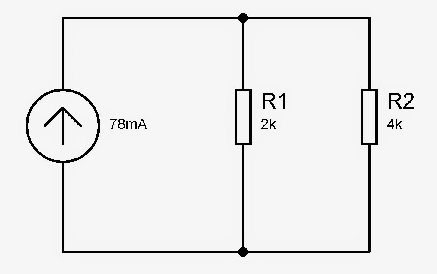
10 The current through R2 is ___ mA.
11 You are programming a 8 bit timer. The
clock frequency is 16Mhz. Prescalar has been set to 64. In one for loop the timer registers gets overflowed
once. What counter will you set for this for loop if you want to count 1
second? (Round of all the other digits to zero except the most significant
digit. For e.g. If your answer is 2301, write it as 2000).
12 What is the degree of freedom of an omni
wheel (holonomic wheel) ?
BELOW
2 In the following figure, for the
output to be 1, what should be the input ABCD?

3 The output V0 of the following circuit is: ___ *
10-2 V.

4 The Capacitance of a ceramic capacitor
with 150 written on centre is ____ pico farad.
7 The resistance of a resistor with
first three color bands Green-Blue-Orange is _____ kilo ohm.
8. Ultrasonic sensors, which are used
mainly to measure the distance emits waves with velocity 340m/s. As soon as the
waves are sent out by the transmitter it sends a HIGH signal to controller, and
when the waves, after getting reflected back from the object/wall again comes
back to the receiver , the signal becomes LOW. You know that the time period
for which the signal was on is X micro seconds. In order to calculate the
distance in centimeters, you must divide
the number X with some value Y. What is
Y?
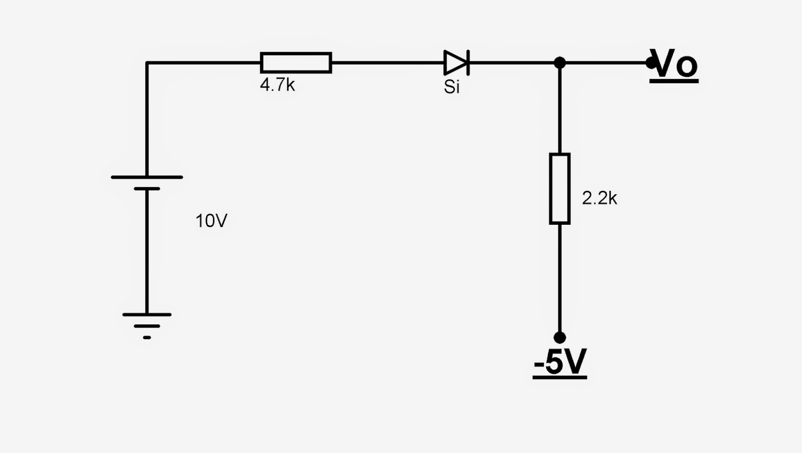
9 The value of Vo in the following
circuit is ___ mV. (ignore the sign if any).
10 The AC voltage spplied in india for
domestic purpose is ___V. (Round of the last digit to zero. +/- 10V will be considered correct. )
11 If Vo = |Vo|
for the following circuit than it will act as which type of gate?
01
EX-OR 02
EX-NOR 03 OR 04 NAND.
Solution:

If you liked this, then also have a look at another crossword puzzle
Monday 29 December 2014
How to set a Simple Timer with Atmega
This program is to show how to write a simple timer in atmel to make your own delay function using the timer.
The basic registers which we will use:


The basic registers which we will use:
1. TCNTx : load the
timer values
Timer 0 and Timer 2 >> TCNT0/TCNT2 >> 8 bit timers hence can store 00 to FF.
Timer 1 >> TCNT1L, TCNT1H >> 0000 to FFFF.
2. TCCRX : Timer / Counter Control Register
This controls the way in which timer will function.
Here our aim is to make a simple delay function so we will focus in last three bits only and set the remaining bits to 0
These are the clock select bits which decides the frequency that will be used to run the timer.
Now suppose you select a prescaler of 64. If the crystal frequency is 16Mhz, then the frequency of timer will become 16/64 = 0.25 Mhz.
hence the TCNTx register will increment 2,50,000 times in a second or say once every 4 micro seconds.
NOTE : if the last 3 bits are 000, that means there is no clock source and the timer wont run..
This way you can turn off the timer.
ANd when TCNTx again becomes zero, TIFR register comes into picture:
3. TIFR : Timer Interrupt Flag register
The bits of this register are the flags whose values will change when the TCNTx register overflows.
The flags are by default zero and when overflow occurs, they are set. This flag has to cleared and to clear the flag, we have to write "1" to it!!
Note : Each timer has its own ISR(Interrupt Service Routine). When overflow occurs, interrupt occurs and the code inside ISR will be executed.
Our code here is very simple..
>> Set the value in TCTN0 register
>> Set the prescaler in TCCR0.
>> Wait till the Overflow occurs.
Waiting is not timers are meant for..
But this makes clear the basic functions of various registers.
Run it in proteus, and you can see the LED blinking.

Get the codes from here:
Subscribe to:
Posts (Atom)